Wednesday May 8, 2013 at 12:10pm
Hi
Design Studies and Optimisation are great tools for exploring how you can improve the design of a part. Design Studies allow you to make changes to Simulation parameters (e.g. loads, materials etc.) as well as dimensions and then monitor the behaviour (e.g. trends in stress or displacement). Optimisation goes even further and fine tunes dimensions to give you the best possible solution within given constraints.
However, when running these studies it can be frustrating to discover that the Design Study or Optimisation has failed due to a geometric rebuild error. For instance, if a fillet is allowed to increase in radius (which will help reduce stress) it might get too big and fail geometrically.
There is an easy way around this - which takes no extra effort. All you need to do is to suppress any Constraints you have in the Design Study and remove the Objective. You can set the Variable dimensions to 'Range' if you have Simulation Professional or 'Range with Step' if you have Simulation. You then hit 'Run' and SOLIDWORKS will build all the combinations of geometry by varying the dimensions. It takes only a few seconds as it is not having to solve FEA studies for each combination. The beauty of this is that you can validate that all the dimensions will work before committing to the full Design Study or Optimisation which will work through all the FEA results.
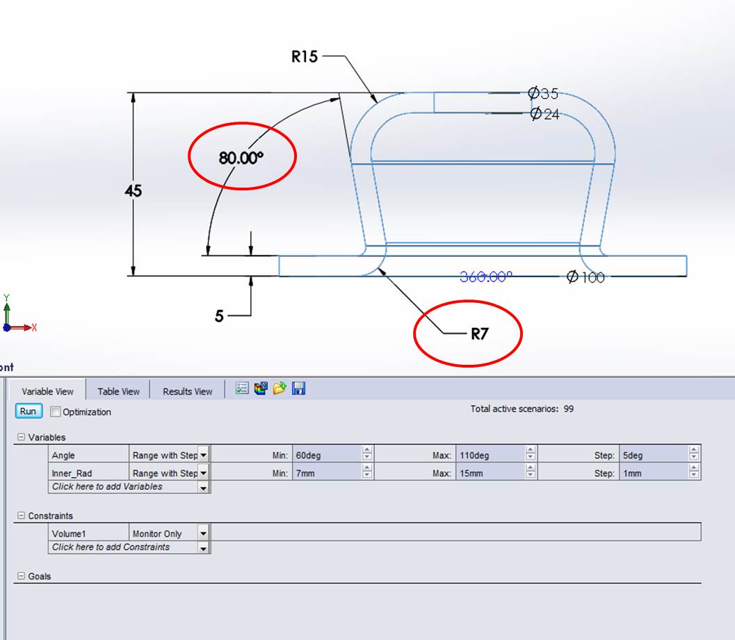
Here is an image of a Design Study Set Up where only the geometry will change. The ringed dimensions can vary and SOLIDWORKS generates 99 results.
Try it on a simple example and you will like it!
Andy Fulcher
Technical Manager
Solid Solutions Management Ltd