Industry Insight: Demonstrating Product Development Cycles
As a collective of Engineers, Designers, and Manufacturers, we thrive on solving practical problems through elegant solutions. So we set ourselves a small but meaningful challenge...
Could we design and manufacture a compact, durable bottle opener that fits neatly on a keyring?
This wasn’t just about creating a novelty item or a theoretical design - it was about demonstrating the complete product development workflow.
We wanted to clearly demonstrate how to take a design from initial concept sketches through to creating 3D CAD models in SOLIDWORKS Design, testing them with Simulation tools & rapid prototyping, before using low volume batch production to manufacture the final product.
Throughout this process, we used all the same tools and services we offer to our clients across the TriMech Group.
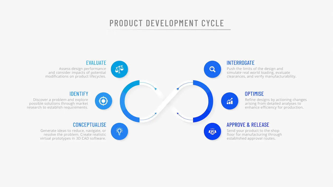
The process of taking a new product to market typically follows these stages:
- Identification: Identify problems and brainstorm new ideas that resolve them and meet business objectives.
- Concept Development: Refine ideas with stakeholders and develop virtual prototypes in 3D CAD.
- Interrogation: Test designs to evaluate materials, performance, and manufacturability.
- Optimisation: Refine designs based on feedback and prepare for production.
- Approval & Release: Designs are released for manufacture and distribution into the market.
- Evaluation: Reviewing performance post-launch and gather insights for improvement.
Phase 1: Identification
To illustrate these stages clearly, we set out to design a simple product that would be easily recognisable and functional.
A bottle opener that was both durable and convenient for everyday use seemed like a suitable route to achieve this. It needed to be slim enough to carry comfortably in a pocket or bag, yet strong enough to handle repeated use.
At the same time, the project was an opportunity to demonstrate the quality and versatility of our design and manufacturing solutions.
Phase 2: Concept Development
We explored two design approaches:
- A flat crown-top opener
- A notched opener
 CAD concepts: crown-top vs. notched opener designs.
 Both design concepts rely on leverage to bend the cap of the bottle sufficiently to remove it from a bottle.
We also wanted to integrate the TriMech Group logo into the design to incorporate our brand identity within the product.
Our research suggested that around 100 N of force is typically required to achieve this fundamental ability.
This figure would go on to influence our design choices, particularly around stress distribution and material selection.
The logo defines the overall profile for the crown-top version, resulting in a distinctive hexagonal form.
Meanwhile we developed a sleeve for the notched version with an embossed logo, adding thickness and surface texture to improve ergonomics.
Phase 3: Interrogation
At this stage, the focus shifted from what it should look like to how it should work under real-world conditions. Several key considerations shaped the design:
- Material trade-offs: Stainless steel was selected for the insert because of its high yield strength and wear resistance, ensuring it could withstand repeated cycles of levering metal caps. The housing was produced in nylon PA12, chosen for its toughness and compatibility with vapour smoothing. While the entire opener could have been made from nylon, incorporating stainless steel gave us the durability and compactness required for long-term, repeat use.
- Assembly philosophy: To simplify production, we avoided adhesives and screws, instead using a keyring clip to fasten through the two components. This approach reduced assembly time and allowed the insert to be removed and reassembled, making it easy to demonstrate tolerances and machining quality.
- Geometry and stress distribution: Rounded transitions were introduced at leverage points to minimise stress concentrations. Thanks to the properties of nylon PA12 and the manufacturing process used, we did not face the same layer-orientation weaknesses typically associated with standard 3D printing methods.
- Simulation insights: Using SOLIDWORKS Simulation (FEA), we modelled the 100 N force required to open a bottle cap. The analysis confirmed that stresses remained well below the yield limits of both materials, giving us confidence in the design’s durability.
- Iteration decisions: Early fastening methods were abandoned in favour of the integrated clip system. We also refined the sleeve thickness to balance ergonomics with strength, while increasing the height of the surface texture to achieve better definition and improved grip.
The Need for Speed: Rapid Prototyping
With support from our additive manufacturing team, we trialled different 3D printing technologies in-house.
Using the Bambu Lab printer, we could move from CAD to physical prototypes in hours and compare results across machines to refine the design quickly.
The crown-top design performed well in testing but required a larger profile than we considered practical for a pocket-sized tool. Its bulk would have made it uncomfortable for everyday carry, so we shifted our focus to refining the notched design.
This alternative gave us the opportunity to concentrate on improving finish, texture, and tolerance while keeping the overall form compact and user-friendly.
Prototypes produced on the Bambu Lab printer for quick iteration. During this stage, we also eliminated one of the notched variations, as the length needed to achieve the correct positioning and leverage compromised the compactness we were aiming for.
Rapid prototyping was essential in validating the geometry quickly and confirm functionality. Once the design was proven, the process naturally progressed to small-batch production, ensuring consistent quality and repeatability. To achieve this, we once again turned to Solid Print3D, utilising their SLS machines. While this stage could have been outsourced to our 3D printing bureau, we chose to keep it in-house to make full use of the wide range of production tools available through Solid Print3D.
Phase 4: Optimisation & Testing
With prototypes in hand, the next step was to validate performance under real-world conditions. Using the Fuse SLS printer, we produced higher-resolution samples that gave us a clearer picture of surface quality, dimensional accuracy, and durability.
Hands-on testing of the prototype to validate function. The testing process focused on three key areas:
- Functionality: Each prototype was used to open multiple bottles to confirm that the geometry translated correctly from CAD to physical part, and that the leverage points aligned as intended.
- Strength and durability: Repeated loading was applied to ensure the stainless-steel insert and nylon housing could withstand the 100 N force required to remove a cap without deformation or premature wear.
- Fit and finish: Tolerances were checked against the CAD model to confirm that the insert seated securely within the housing, while surface texture and embossed logo definition were evaluated for both ergonomics and aesthetics.
These tests confirmed that the notched design performed consistently and comfortably, validating the refinements made during development. The results gave us confidence that the design was not only functional but also production-ready, with no significant deviations between the digital model and the manufactured part.
Phase 5: Approval & Release for Manufacture
For the final stage, we leveraged the wider TriMech Group collective to combine precision, scalability, and finish quality.
Plastic sleeves were produced by 3DPRINTUK, specialists in additive manufacturing at scale, selecting MJF nylon (PA12) for its strength, resilience, and excellent surface finish.
Plastic sleeves produced by 3DPRINTUK in MJF nylon PA12, vapour smoothed and dyed black. After printing, the parts were vapour smoothed and dyed black, giving them a professional, injection-moulded appearance. This process not only enhanced durability but also ensured a consistent, high-quality aesthetic suitable for a production-ready product.
Metal inserts were manufactured in-house by Solid Print3D using the XTOOL machine. The inserts were cut from 3 mm stainless steel with minimal waste, then tumbled to remove sharp edges and achieve a smooth, user-friendly finish.
Stainless steel inserts cut on the XTOOL machine and finished through tumbling. Phase 6: Evaluation
For this stage, we were primarily interested in the cost of production and the commercial viability of our product, assuming suitable market interest.
Using 3DPRINTUK’s online cost calculator, we estimated that producing the nylon sleeves at small-batch volumes would cost approximately £0.89 per unit.
The stainless-steel profile added around £0.60, and a simple lobster clasp contributed a further £0.11, bringing the total production cost to roughly £1.60 per unit.
These figures gave us confidence that the design was not only technically robust but also commercially practical, demonstrating how small-batch additive and subtractive manufacturing can deliver both performance and affordability.
How do you know when to opt for 3D printing over injection moulding? Discover more with 3DPRINTUK and a variety of additive manufacturing options, or consider the hardware available from Solid Print3D.
By combining 3DPRINTUK’s expertise in polymer batch production with Solid Print3D’s precision metalworking and rapid prototyping, we demonstrated how the TriMech Group can deliver a complete, integrated workflow.
Our clients benefit from this collaboration by accessing a full suite of design, simulation, prototyping, and manufacturing services under one roof
So whether you prefer to handle design, simulation, and prototyping in-house or offload the workload through our dedicated bureau services, the TriMech Group provides the flexibility to support your project at every stage.
If you're interested in exploring how SOLIDWORKS, simulation, or additive manufacturing could streamline your own projects, then please get in touch with the Solid Solutions team and we’ll help you turn ideas into engineered reality.